
Quick answer
Send an editable solid model or a neutral STEP file for each custom game piece. Add a PDF drawing that records units, critical dimensions, tolerances, material, color, finish, decoration and cosmetic restrictions. An STL can help with visual review or prototyping, but it should not be the only file in an injection molding package. Keep every part name and revision consistent across the model, drawing, artwork and component list.
A model that looks finished on screen may still leave a toolmaker guessing. A game designer sees a pawn, token or miniature. A mold engineer sees separate questions about parting direction, draft, wall thickness, undercuts, gate position, ejector marks and the surfaces players will touch.
The goal is not to design the mold yourself. Your job is to send an unambiguous product definition. The manufacturer can then review moldability without spending the first round of communication working out which file is current or what a dimension was meant to be.
1. Choose the right 3D file format
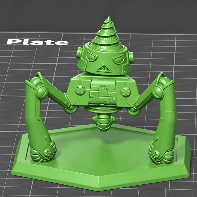
For cross-platform exchange, start with a STEP file using the .step or .stp extension. If the manufacturer uses
the same CAD system, include the native part file as well. The native file
may retain sketches, features and design history that make a revision
easier.
STL has a different job. Autodesk describes STL as a unitless, triangulated surface and notes that flat facets approximate the original shape. That makes STL useful for 3D printing and visual reference, but less suitable as the only source for mold design. Autodesk also describes STEP as an international 3D exchange format. See the official Fusion export format documentation.
| File | Best use | What to watch |
|---|---|---|
| STEP (.step, .stp) | Primary neutral solid model for manufacturing review | Open the exported file and confirm that all intended bodies and surfaces transferred correctly. |
| Native CAD | Design changes when both parties use compatible software | External references, linked parts and version differences may break when the file moves to another system. |
| IGES (.igs, .iges) | Fallback neutral exchange format | Check imported surfaces for gaps and missing faces. |
| STL (.stl) | Visual reference, scan data or prototype printing | The file is a mesh and may not contain reliable units or editable solid geometry. |
| PDF drawing | Dimensions, tolerances, notes, material, color and finish | A PDF supports the 3D model. It does not replace the model for a complex molded part. |
A practical package contains the native CAD file, a STEP export and a PDF drawing. The extra file is useful when one format imports badly or a small change is needed during DFM review.
2. Clean the model before export
Export the product you want quoted, not the state of your working CAD folder. Suppressed experiments, hidden duplicate bodies and leftover construction geometry create avoidable questions. Open the exported STEP file in a fresh window before sending it.
- Confirm the unit system and one known overall dimension.
- Check that the model imports as a closed solid where the design calls for a solid part.
- Remove duplicate, hidden or obsolete bodies from the export.
- Make separate physical parts into separate CAD bodies or files.
- Keep intended holes, slots, ribs, bosses, logos and texture geometry.
- Remove scenery, render lights, cameras and presentation-only objects.
- Check fine text and small decorative details at actual manufacturing size.
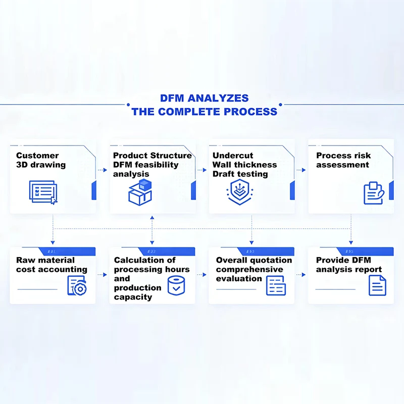
Do not add draft, split lines or gates at random just to make the model appear "mold ready." If you already know the preferred pull direction, cosmetic face or no-gate area, mark it clearly. The mold engineer can then propose the remaining changes during DFM analysis .
3. Separate and name every component
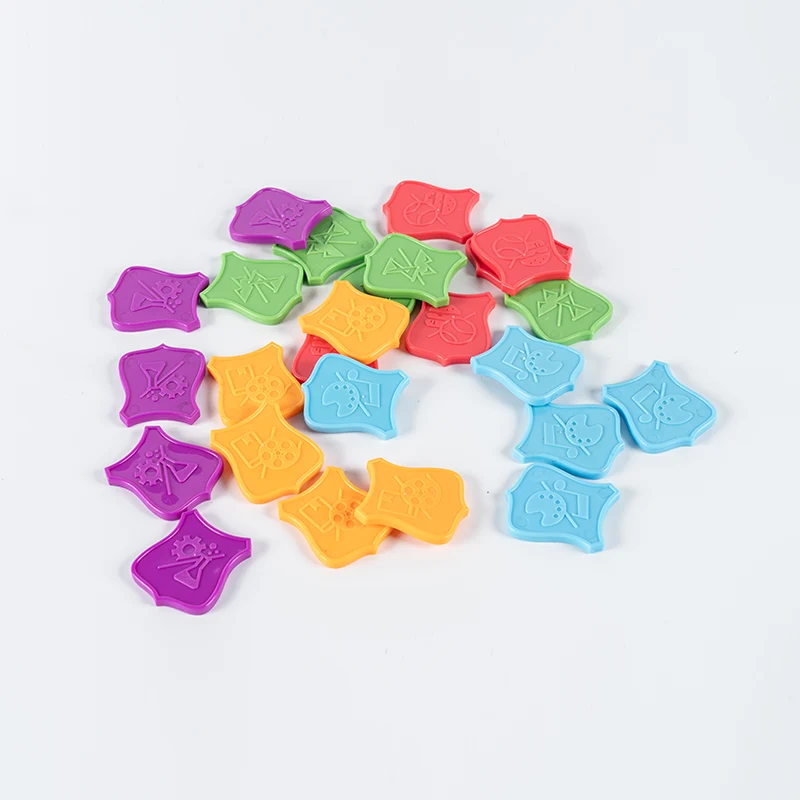
A board game may have pieces that look almost identical but carry different values, colors or symbols. Treat each distinct molded shape as a separate part number. Color variants can share a geometry number, but the color suffix must stay consistent in the component list and artwork.
A simple naming system might look like this:
BG101-PAWN-R1.step | BG101-PAWN-R1.pdf | BG101-PAWN-RED-R1.ai
The exact naming convention matters less than consistency. Avoid filenames
such as final.step, final-new.step and final-new-2.step. They do not tell the manufacturer which file
replaced which.
| Part number | Description | Geometry variants | Color variants | Quantity per game |
|---|---|---|---|---|
| BG101-P01 | Player pawn | 1 | Red, blue, green, yellow | 4 |
| BG101-T01 | Resource token | 3 symbols | Gold | 24 |
| BG101-H01 | Card holder | 1 | Black | 2 |
The values above are an organizational example, not a manufacturing specification. Replace them with the actual contents of your game.
4. Add a 2D manufacturing drawing
The 3D model defines nominal shape. The drawing records requirements that the model cannot show reliably. Keep the drawing readable and focus attention on features that affect function, assembly, appearance or player use.
Include these items on the drawing
- Part name, part number, revision and drawing date.
- Units and a few reference dimensions that make scale easy to verify.
- Critical dimensions and tolerances for mating or moving features.
- Material request, or the performance conditions the material must meet.
- Color reference, preferably a named system and code agreed with the supplier.
- Surface finish, texture, gloss or decoration requirements.
- Cosmetic surfaces and areas where gate or ejector marks are not acceptable.
- Logo, text and symbol orientation.
- Any inspection method that is part of acceptance.
Mark the dimensions that control fit or function and discuss the rest during DFM. An unnecessarily tight general tolerance can complicate tooling, inspection and process control without improving the way the game works.
If you do not know the resin grade yet, describe the actual need instead of guessing. Relevant information may include rigidity, impact exposure, repeated flexing, expected appearance, contact with other parts and the market where the finished game will be sold. Material selection and compliance still need project-specific review.
5. Show assembly and fit relationships
A single part file cannot explain how a card holder grips a card, how a lid snaps onto a tray or how a rotating piece is supposed to move. Send an assembly file or an exploded PDF that shows where every component belongs.
Call out the relationships that affect play:
- Parts that snap, slide, rotate, stack or nest.
- Pieces that must fit into a box insert or storage tray.
- Card, board or token thickness at contact points.
- Metal inserts, magnets, pins or purchased hardware.
- Intentional clearance, friction or detent behavior.
Reference models for cards, magnets or packaging can stay in the assembly, but label them as purchased or reference-only parts. Otherwise, they may be mistaken for items included in the molding quote.
6. Prepare color and decoration files
Keep printing artwork separate from the 3D manufacturing model. A rendered texture can show intent, but it is not production artwork. Supply a vector file when possible, plus a PDF proof that shows placement and orientation.
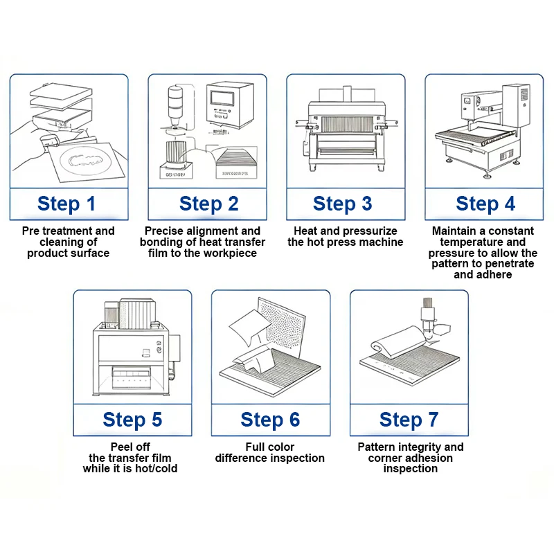
For UV printing, pad printing, screen printing, hot stamping or heat transfer, include:
- Artwork at final size in AI, EPS, SVG or print-ready PDF format, subject to supplier confirmation.
- Outlined fonts or the required font files.
- Named color references instead of screen appearance alone.
- A dimensioned location or registration point on the part.
- Separate layers for each color, white ink, varnish or foil where applicable.
- A visual proof that confirms which side faces up and how the artwork rotates.
The suitable decoration process depends on the part geometry, image detail, color count, surface and production plan. Review the available UV printing and surface finishing services before locking the artwork.
7. Control filenames and revisions
A small geometry edit can affect tooling, decoration and assembly. Give each issued package a revision code, and use the same code on every related document. If only one file changes, explain whether the other files remain valid.
- Freeze the issue package. Create one folder that contains only the files released for review.
- Add a revision note. List the changed parts and describe the change in plain language.
- Replace obsolete files clearly. Do not leave two current-looking models in the same folder.
- Ask for receipt confirmation. Confirm the manufacturer is reviewing the intended revision before DFM or tooling begins.
A practical folder can be organized like this:
 /BG101_R1/3D/ | /BG101_R1/2D/ | /BG101_R1/ARTWORK/ |
    /BG101_R1/ASSEMBLY/ | /BG101_R1/README.pdf
8. Run the submission checklist
Before you send the package, open it as if you were the supplier receiving it for the first time.
- Every molded shape has a unique part number.
- The native model and STEP export carry the same revision.
- The STEP file opens at the correct scale.
- The component list matches the number of CAD files.
- The drawing identifies units, material request, color and finish.
- Critical fit dimensions and cosmetic restrictions are marked.
- Assembly references are labeled and cannot be mistaken for quoted parts.
- Artwork has final size, colors, orientation and placement information.
- Quantities are stated per game and for the planned production order.
- The README lists open questions instead of hiding assumptions in email threads.
Minimum quote-ready package
| Deliverable | Purpose |
|---|---|
| STEP file for each molded shape | Defines the nominal 3D geometry for review. |
| PDF manufacturing drawing | Records dimensions, tolerances, materials, finishes and restrictions. |
| Component list | Connects part numbers with colors and quantities. |
| Assembly or exploded view | Shows fit, movement and the relationship between parts. |
| Artwork and placement proof | Defines printed or decorated graphics. |
| Revision note | Identifies the current issue and what changed. |
9. What happens after submission
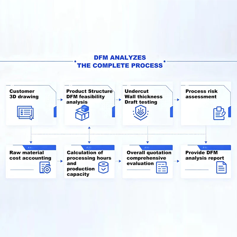
The first response should not be a blind tooling approval. The manufacturer needs to review geometry, expected quantity, material, appearance and the way each part fits with the rest of the game.
- File check. The supplier confirms that the package opens, the scale is correct and the part list is complete.
- DFM review. The mold engineer checks draft, undercuts, wall transitions, possible parting direction, molding marks and other process risks.
- Questions and revisions. You decide which proposed changes are acceptable and issue a controlled revision.
- Quotation alignment. The quote should refer to the reviewed files, quantities, materials, finishes and included operations.
- Approval before tooling. Both parties confirm the released revision and unresolved assumptions before mold work starts.
For the broader path from method selection through production, read the custom board game components manufacturing guide .
10. Frequently asked questions
Can I send only an STL file?
You can send STL as a visual or prototype reference, but ask the manufacturer whether it is suitable for the next step. For injection molding review, include an editable solid or STEP file whenever possible. STL represents the shape as a mesh and may not carry reliable units.
Do I need to add draft angles before requesting a quote?
You do not need to guess. Mark the preferred pull direction, cosmetic faces and features that cannot change. The manufacturer can review draft during DFM and explain which surfaces need revision.
Should different colors be separate CAD files?
Not when the geometry is identical. Use one geometry number and list each color variant in the component schedule. If the symbol, texture or molded shape changes, give the variant its own part number.
Can the manufacturer repair or modify my model?
Minor changes may be possible, but the scope depends on the source file and the design issue. Keep ownership of the design decision clear. Review every revised model and drawing before it becomes the tooling reference.
What if I do not know the final plastic material?
Describe the part's use, appearance, flex or impact needs, mating parts and target market. The supplier can discuss candidate materials, but the final choice still needs agreement and any required compliance review.
Have a board game component ready for review?
Send the current CAD package, component list, target quantity and open design questions. Kingke can review the files before quoting custom plastic parts.
Send your project files