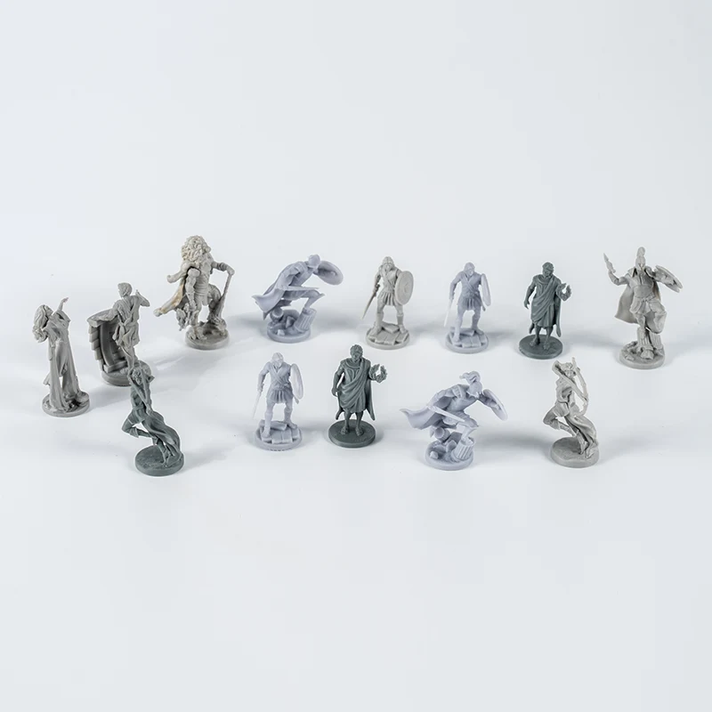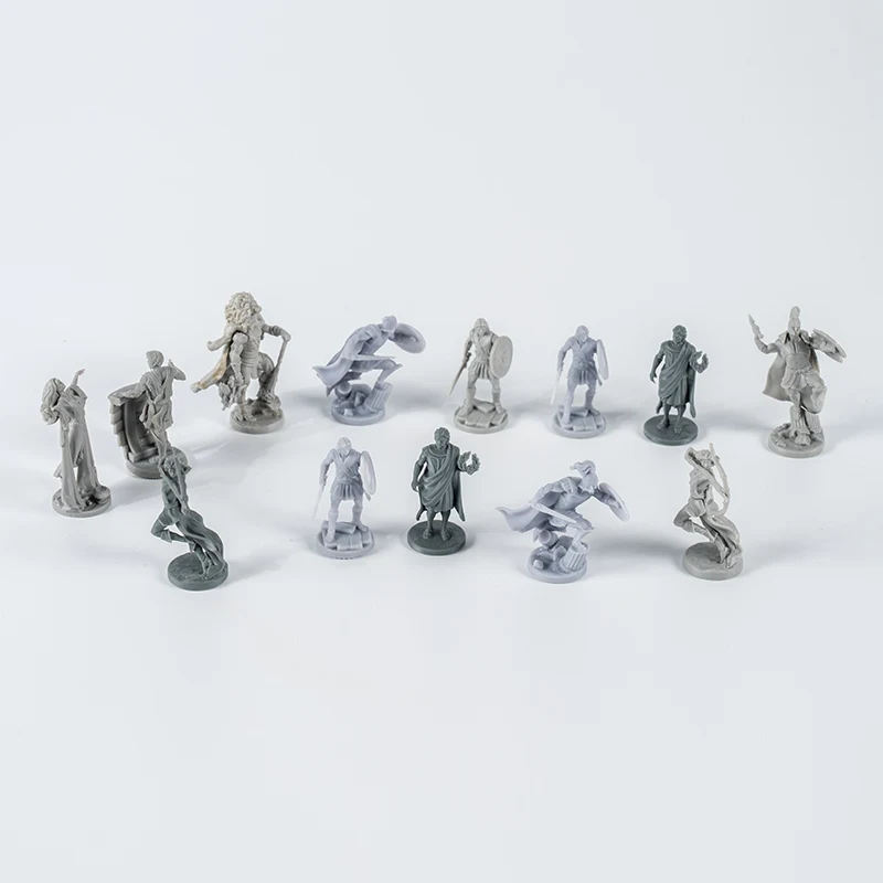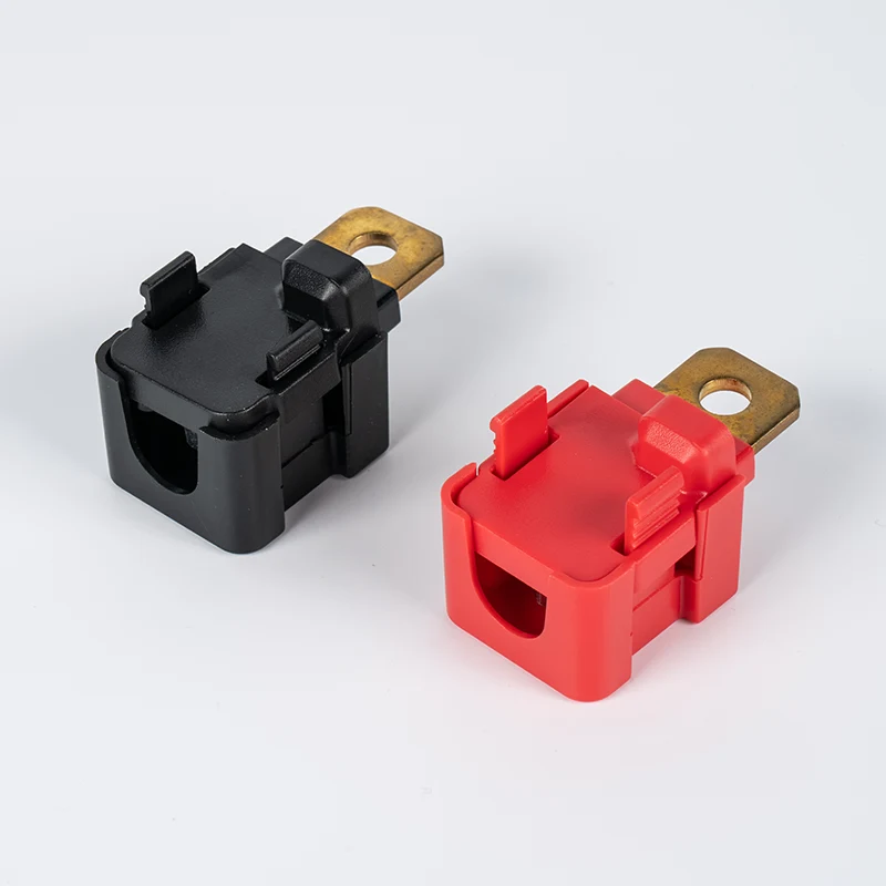

A game piece can look solid while behaving like several different parts during molding. A thick base holds heat. A narrow stem restricts flow. A raised emblem creates a local mass behind a visible face. Wall-thickness design connects those regions so the cavity can fill, cool and shrink without turning the product into a sink-mark or warpage problem.
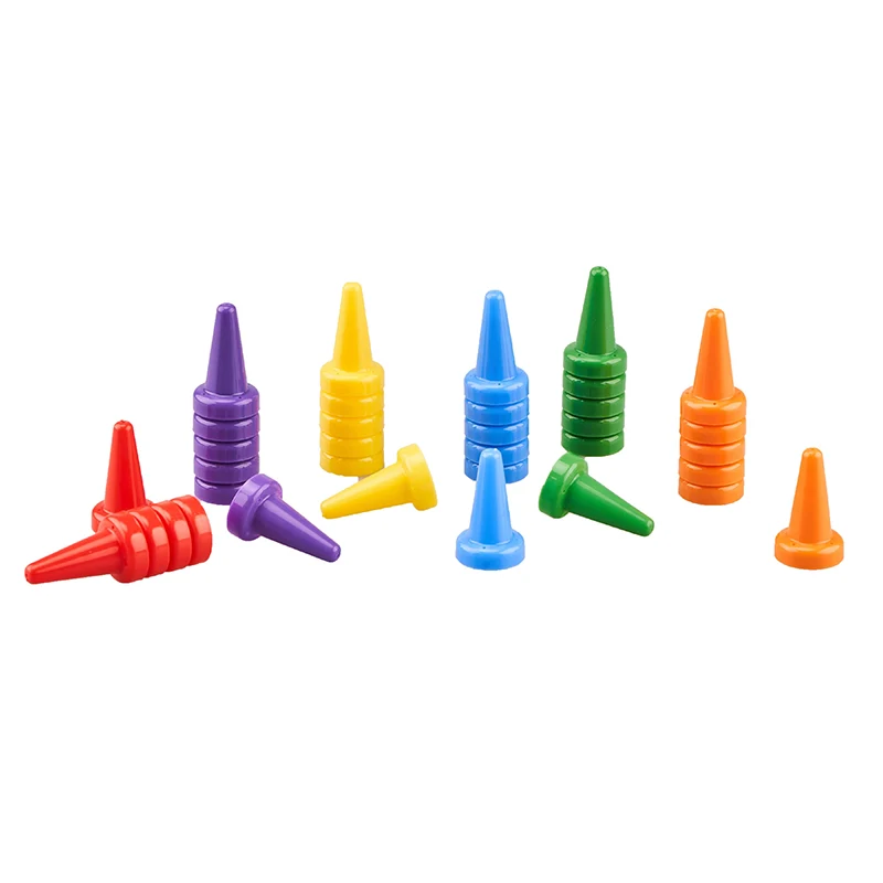
Quick answer
Choose one nominal wall thickness for the main shell, then map every region that is thinner or thicker. Core out heavy bases and solid masses where the hidden geometry allows it. Use ribs, gussets and bosses to provide local support without recreating a thick block at their roots. Blend required changes gradually, and review the wall map with the selected resin, gate position, cooling layout and cosmetic surfaces. There is no safe universal number for every pawn, token or miniature.
1. Start with a nominal wall, not a random range
The nominal wall is the baseline thickness of the main molded shell. It gives the designer and mold engineer a common reference for ribs, bosses, transitions and local exceptions. It is not a promise that every point on a sculpted miniature will measure exactly the same.
Autodesk describes even wall thickness as the preferred direction because thickness affects both filling and cooling. Thin areas resist flow and may remain unfilled. Thick areas cool more slowly and can contribute to sink or warpage.[1] The design task is to control the exceptions rather than pretend they do not exist.
Set the nominal wall after the following inputs are known:
- The exact resin grade or a clear performance brief for material selection.
- The longest expected flow path from the proposed gate.
- The stiffness, impact, flexing and assembly requirements.
- The visible faces, texture and decoration zones.
- The component's overall scale and the smallest must-fill detail.
- The planned cavity count and production process.
A drawing marked only "ABS/PP" does not provide enough information. Resin families contain grades with different flow, shrinkage and mechanical behavior. The guide to ABS versus PP for board game components explains why the application and exact grade must be considered before tooling.
2. Thin and thick sections fail in different ways
A thin region can freeze before the cavity is full. The result may be a short shot, hesitation mark or an area that needs higher filling pressure. A thick region creates a different timing problem: the outside skin solidifies while the center remains hot and continues to shrink.
Autodesk attributes sink marks and internal voids to localized shrinkage at thick sections without enough compensation. Ribs, bosses and internal fillets can create those local masses on the opposite side of a visible wall.[2] A process adjustment may improve packing, but it cannot make a poorly placed block of plastic disappear.
| Thickness condition | Likely molding concern | Game-piece symptom | First design check |
|---|---|---|---|
| Long thin flow path | The melt front loses heat and pressure before reaching the end. | Incomplete blade, hand, rim or narrow token edge. | Review the gate, resin flow behavior and local wall together. |
| Abrupt thin-to-thick step | Flow and cooling change suddenly at one location. | Visible line, distortion or local packing difference. | Replace the step with a gradual transition where geometry permits. |
| Solid heavy base | The center cools and shrinks later than the outer skin. | Sink, internal void, extended cooling or a distorted standing plane. | Core the hidden underside and preserve a controlled shell. |
| Heavy rib root | The rib and wall combine into a local thick section. | Depression on the opposite cosmetic face. | Reduce rib thickness and inspect the root radius. |
| Boss attached to a wall | The junction creates a mass larger than either feature alone. | Sink near a peg, screw feature or assembly post. | Stand the boss away and connect it with thinner supports. |
| Uneven flat token | Different regions cool and shrink by different amounts. | Curling, rocking or poor stacking. | Map thickness across the full face, including raised icons and borders. |
3. Build a wall-thickness map before changing the model
A sectional drawing shows one cut. A wall-thickness analysis shows the local thickness throughout the three-dimensional part. Use both. The color map finds unexpected masses around corners and intersections; sections explain how those regions were created.
Classify each area as nominal, intentionally thin, intentionally thick or unresolved. Then add a reason. "Thick for balance" is useful. "Thick because the original sculpt was solid" is not a product requirement.
The map should identify:
- The nominal wall and the tolerance basis used for review.
- The thinnest flow-critical paths and distant details.
- The thickest local masses, including hidden intersections.
- Rib, boss, gusset and raised-logo roots.
- Areas where the material changes direction sharply.
- The gate, last-to-fill zone and expected packing path.
- Cosmetic faces on the opposite side of each internal feature.
Do not judge a miniature only by the outside surface. A narrow neck can contain a large solid core while a broad cape can be a thin shell. The thickness map reveals the material section that the melt and cooling system encounter.
4. Core heavy bases and solid masses from a hidden side
Coring removes plastic from the center of a thick feature while leaving the outer form. For a pawn, the opening may sit under the base. For a miniature, a shell can replace a solid torso where the tooling and parting strategy allow it. For a holder, pockets beneath a thick platform can reduce material without changing the top surface.
Eastman's mold-design guide recommends coring thick sections when uniform walls are otherwise difficult to achieve. It also notes that the coring pattern can incorporate ribs, gussets and bosses.[4] This is a structural redesign, not a blind subtraction operation.
Check these consequences before approving a cored base:
- Standing stability: keep the actual contact ring flat and free from gate or ejector interference.
- Perceived weight: confirm that the lighter sample still feels appropriate during play.
- Impact path: retain enough structure between the stem, shell and base edge.
- Release: add suitable draft to the new internal walls and avoid hidden undercuts.
- Cooling: give the mold designer access to cool the remaining heavy regions.
- Appearance: inspect the visible outer surface over the cored and ribbed structure.
If the game needs extra weight, do not assume a solid plastic mass is the only option. The product team can compare geometry changes with a separate insert or another approved construction. Any insert plan needs its own assembly, retention and safety review.
The shell still has to fill, support the piece and survive use. Remove the concentrated mass, then verify the new flow path, stiffness, balance and ejection conditions.
5. Use ribs and bosses without rebuilding the thick section
Ribs add stiffness by changing the shape of a section. A boss provides a cylindrical feature for alignment, fastening or another local function. Both can reduce the need for a thicker main wall, but both also create material intersections.
Stratasys recommends keeping a rib thinner than the nominal wall and reports a general starting limit of 60 percent for the rib base. The same guide applies a similar starting point to boss walls.[3] Eastman gives a roughly one-half-wall starting point for its polymers.[4] These are qualified design guides, not universal acceptance limits. The resin, finish, rib height, gate position and opposite face can change the result.
Review a rib or boss with five separate questions:
- Is the feature needed for stiffness, alignment or assembly?
- Is its base thinner than the wall it joins?
- Does the root radius reduce the abrupt corner without creating a new heavy mass?
- Does the sidewall have enough draft for release?
- What cosmetic surface lies directly opposite the junction?
A boss pushed against a sidewall combines both thicknesses into one corner. Moving it away and joining it with thinner gussets can preserve support while reducing the local mass. Section views should show the full intersection as well as the boss diameter.
6. Blend thickness transitions where geometry must change
Some variation is unavoidable. A pawn stem must meet its base. A token edge may need a rim. A card holder needs a thicker load path near the slot. The problem is the abrupt step, where flow and cooling behavior change at one sharp boundary.
Use a taper, curve or staged transition where the product shape allows it. The change should be long enough for the melt path and section stiffness to change progressively. There is no one transition length that suits every material and geometry, so show the before-and-after section in the DFM report.
Inside fillets also need restraint. A radius can improve flow and reduce a sharp stress concentration, but an oversized radius at a wall intersection adds material to the corner. Inspect the local thickness after fillets are applied. The visually smoothest CAD blend is not automatically the most uniform molded section.
Fillets, chamfers, embossed logos and shell operations can change the wall map. A clean early model does not prove that the released model remains uniform.
7. Wall thickness and gate location must be reviewed together
The gate determines where the melt enters and how holding pressure reaches thicker regions. A thin section between the gate and a heavy base can freeze first, limiting the pressure available to compensate for later shrinkage in that base. Moving the gate may help packing, but it can also move the gate witness, weld line and air-trap location.
The article on gate locations for board game pieces provides a candidate-comparison method based on the visible mark, flow path, meeting line and last-to-fill zone. Add the wall-thickness map to the same review.
Use these combined checks:
- Trace the flow from the gate through every thin restriction.
- Identify thick regions that need holding pressure before the path freezes.
- Check whether thick sections attract flow and create an unbalanced fill pattern.
- Mark where changing thickness moves weld lines or the last-to-fill area.
- Compare gate alternatives without sacrificing a protected face or standing plane.
Autodesk includes gate relocation among the possible responses to sink marks because a closer gate can improve packing of a thick area.[2] The same guidance warns that one correction can introduce another problem. Geometry, gate, runner and process need a joint review.
8. Check the exact resin grade before freezing the wall
Wall thickness is a relationship between geometry and material flow. Two grades from the same resin family may need different decisions because their viscosity, shrinkage, stiffness, filler and impact package differ. Colorant and recycled content can also change the production behavior and appearance, so the final purchase specification matters.
Use a material data sheet and the molder's process knowledge to confirm:
- Recommended wall-thickness range for the exact grade.
- Flow behavior over the planned path and gate arrangement.
- Mold shrinkage data and whether direction matters.
- Expected stiffness and impact at the intended section.
- Surface, coloring, printing and bonding requirements.
- Any compliance or end-use conditions supplied by the buyer.
Kingke's board game plastic components range includes custom shapes, colors, textures and printed designs. Those choices should reach the wall-thickness review early because a cosmetic surface can make a small sink more visible, while a print zone may require better flatness than an undecorated part.
9. Apply the logic by game-piece type
Pawns and standing figures
Start with the base-to-stem section. A heavy base may help stability, but a solid mass can cool differently from the stem. Core from the underside where possible, retain a flat contact ring and use sections to show how load moves from the stem into the shell. On custom plastic pawns, pose and proportion can change that load path.
Miniatures with thin details
Map the flow path to arms, weapons, hair and clothing edges. A detail may be thick enough to exist in CAD but too restrictive at its root or too distant from the gate for the selected material. Thickening the tip alone may not help if the melt cannot reach it. Check the whole path from the body or base.
Tokens and tiles
Flatness and stacking make thickness variation visible in use. Raised symbols, recessed art panels, rims and texture can change the section across an apparently flat token. Review both faces and keep local masses away from the opposite cosmetic area. The plastic token page shows why molded shape and printed decoration need one approval plan.
Cubes and rigid accessories
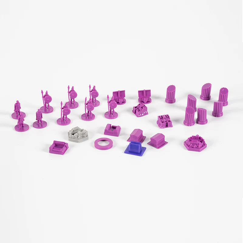
A cube-shaped component does not have to be a solid block. Internal coring can control mass, but the shell, corners, gate and ejector surfaces must still be designed as a system. For tabletop game plastic cubes, stable stacking and usable printed faces are product requirements that should appear on the wall map.
10. What a wall-thickness DFM review should show
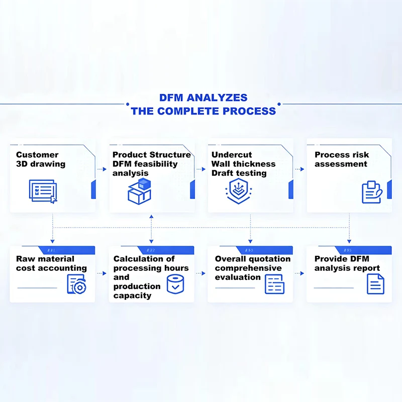
Kingke's DFM analysis service lists wall-thickness uniformity, ribs, shrinkage, deformation and mold feasibility among its review areas. Ask for evidence tied to the exact model revision rather than a generic pass or fail.
| DFM item | What it should contain | Decision it supports |
|---|---|---|
| Thickness color map | Legend, model revision, nominal wall and flagged local extremes. | Find hidden masses and restrictive regions across the full part. |
| Section set | Cuts through the base, stem, ribs, bosses, raised details and mating features. | Explain how the color-map regions were created. |
| Coring proposal | Before-and-after geometry with standing, weight and ejection notes. | Reduce solid mass without losing product function. |
| Rib and boss review | Base thickness, height, radius, draft and opposite cosmetic face. | Support the part without creating new sink zones. |
| Fill and pack review | Selected resin, gate location, thin restrictions and thick packing zones. | Check whether the cavity can fill and receive pressure as intended. |
| Cooling concept | Heavy areas, core cooling limits and expected retention differences. | Plan the mold around the actual thermal mass. |
| Open assumptions | Unconfirmed resin, color, texture, decoration or load requirements. | Prevent a provisional geometry check from becoming a final release. |
Kingke's precision injection mold design service covers DFM, cavity layout, runners, cooling, venting and ejection. Those mold systems should be overlaid on the thickness review. A cored base that looks better in the product CAD may create a difficult cooling or ejection condition if the tool structure is ignored.
11. Inspect molded samples against the wall map
The first sample should be read as evidence about the design, mold and process. Mark each observation on the same view used for the wall-thickness review. This makes it easier to test whether a sink sits opposite a rib, a short shot lies beyond a thin restriction, or a warped base follows an uneven section.
Inspect:
- Cosmetic faces under consistent lighting for sink and gloss changes.
- The standing plane on a flat reference surface.
- Stacking and mating parts using production counterparts.
- Thin distant features for complete filling and distortion.
- Rib and boss areas for opposite-face depressions.
- Cavity-to-cavity consistency with part identity preserved.
- The final decorated surface after printing, painting or coating.
Keep material, color, cavity, sample date and process revision with the photographs. One attractive piece is not enough to separate a stable result from a favorable shot. The injection molding defects guide provides a broader diagnostic sequence for short shots, sink, warpage and ejection damage.
If a geometry change is needed, update the wall map and repeat the affected analysis. Kingke's plastic injection mold service includes mold testing and sample validation, which should remain tied to the approved product revision.
Frequently asked questions
What wall thickness should a plastic board game piece have?
There is no universal wall thickness for every game piece. The value depends on the exact resin grade, flow length, gate position, geometry, strength target, appearance and molding process. Set one nominal wall as a design baseline, map unavoidable variations, and ask the mold designer to confirm the final values during DFM.
Why should a thick pawn base be cored out?
A solid base can create a large local mass that cools and shrinks differently from the thinner stem and outer skin. Coring removes material from a hidden area while keeping an outer shell and any needed ribs. The revised base still has to meet weight, balance, strength, gate and ejection requirements.
Do ribs replace thicker walls?
Ribs can add stiffness without thickening the whole part, but their base creates a local thickness increase where it joins the main wall. Keep the rib thinner than the nominal wall, add a suitable root radius and draft, and check the opposite cosmetic surface for sink risk.
Can wall thickness fix a short shot?
Changing a thin or restrictive section can improve filling, but a short shot may also come from gate location, venting, resin flow behavior or process settings. Mark the incomplete area, compare cavities and review the full flow path before changing the product geometry.
Should a prototype have the final injection-molded wall thickness?
The prototype should represent the intended production geometry when it is used to check fit, balance and handling. A 3D-printed sample may not reproduce injection-molded stiffness, shrinkage or surface behavior, so its results should be treated as design evidence rather than proof of the final molding process.
Need a wall-thickness review before tooling?
Send the latest 3D model, intended resin, component quantities, critical dimensions, cosmetic-face notes and weight or balance requirements. Kingke can review wall sections, coring, ribs, gate interaction and the proposed mold structure.
Request a DFM review