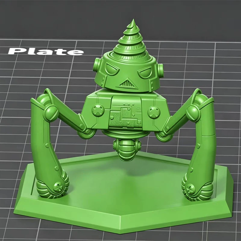

Choose a one-piece miniature when the required sculpt can be molded and removed from the tool with an acceptable design and tooling arrangement. Evaluate a multi-part miniature when a split helps preserve a pose, reach difficult geometry or meet an assembly requirement. Then decide who assembles it: the factory or the player.
Our recommendation is to approve the split, connection and finished delivery state together. A lower molded-part price is not enough if assembly and packaging change the comparison.
In custom board game production, miniatures are one group of components, but their construction can create decisions that a parts list alone does not explain. A shield may be integral, attached before packing or supplied separately. All three can represent the same character, yet they ask different things of the mold, assembly process and buyer.
This guide focuses on injection-molded plastic miniatures. For the wider component and process choices, start with our board game components manufacturing guide.
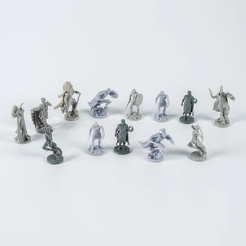
1. One-piece and pre-assembled describe different things
One-piece describes the manufacturing structure. Pre-assembled describes the condition in which the miniature arrives. They are not interchangeable terms.
A one-piece body can still have a separate base. A finished miniature can contain a separately molded arm that the factory attaches. Define whether the base, weapon and accessories belong to the construction being compared before asking for a quote.
| Route | Manufacturing structure | What the player receives | Main review task |
|---|---|---|---|
| One-piece construction | The agreed miniature scope is molded as one part. | A finished figure, subject to any separately specified base or accessory. | Can the required shape fill, release and meet the agreed appearance? |
| Factory-assembled miniature | Separate molded components are joined before delivery. | A figure ready for play, without the player's assembly step. | Can the factory locate, join and inspect the parts consistently? |
| Player-assembly kit | Separate components are supplied for later assembly. | A set of parts with the agreed instructions and accessories. | Can the intended user identify, orient and assemble the parts as specified? |
The two halves of a mold do not mean that the figure is manufactured in two parts. A core and cavity can form one component. The mold parting line and a joint between separately made components are different features.[1]
2. Start with the player's first session
Specify the opening experience before choosing an assembly route. If the game should be playable as soon as the pieces leave the tray, both an integral figure and a factory-assembled figure deserve consideration.
Ready-to-play games and hobby kits
A miniature hobby product may make assembly part of its appeal. A family or strategy game may treat it as an obstacle. Instead of assuming a universal preference, write the requirement: whether players need glue, tools, trimming or time before their first game.
Painting access and customization
A separate shield can make the area behind it more accessible before assembly. That benefit disappears for the player if the factory permanently attaches the shield first. Specify whether painting happens before delivery or after purchase, and which surfaces need access.
Storage after assembly
Check the assembled silhouette against the insert, not just the loose parts. A kit that fits the box before assembly may need different storage once the weapon or arm is attached. Repeated removal should only be part of the product concept if the connection is designed and checked for it.
3. What makes a sculpt difficult to mold in one piece?
The question is whether the proposed tool can form and release the shape while preserving the features that matter. Part design, shrinkage, removal, melt delivery and mold structure must be considered together.[1]
Pull direction, undercuts and open poses
A raised arm, a shield held away from the chest or a hooked feature can create areas that need an undercut review. The answer may be a different pull direction, a local shape change, a slide or other tool feature, or a split. An undercut is a reason to assess the design, not an automatic instruction to cut the model apart.
From the manufacturing side, we would first mark what must stay unchanged. If the face, weapon angle and shield position define the character, those are constraints for the tool review. If a small pose adjustment is acceptable, assess it before committing to another component and connection.
Thin features and the end of fill
A long, thin sword needs more than a visual check. Review its section, distance from the gate, material and filling conditions. A feature can look convincing in a render and still need changes for filling or removal. There is no useful universal minimum thickness for every weapon, resin grade and miniature scale.[1]
Detail, ejection and protected surfaces
Ask where the parting line, gate and ejection contacts would be. A proposal that preserves detail but puts an unacceptable mark on the face has not met the appearance requirement. Review the model from the player's normal viewing angles as well as the mold designer's direction.
Our 3D model optimization service covers structural issues including draft, wall thickness and undercuts. The corresponding injection mold design review considers parting, gates, ejection and tool mechanisms. These are related reviews, not substitutes for a molded sample.
4. When splitting the miniature is worth evaluating
A proposed split should solve a named problem. "More parts allow more detail" is too broad to approve a design. Identify which surface, pose, access requirement or tooling constraint becomes easier to manage, then list what the new connection adds.
Preserving poses and separating accessories
Separating a shield arm, base or weapon may provide another way to orient a component in the tool. But separating one accessory is a different manufacturing scope from dividing the whole figure into many pieces. Review only as much splitting as the product needs.
Material choice and connection requirements
When choosing materials for a board game, the miniature's connection deserves its own review. Our Small Plastic Action Figure page lists ABS, PP and PC among its material options. That list is a starting point for discussion, not evidence that any grade will suit a fine sword, snap feature or bonded joint.
If bonding is proposed, confirm the actual substrates and surface condition. Polypropylene is a low-surface-energy plastic that needs suitable bonding selection; 3M's guidance discusses dedicated solutions and asks designers to consider substrates, joint design, stress and environment.[3] Do not assume the adhesive used on a printed prototype transfers to the molded material.
Additional handling is part of the design
A split adds parts to identify, protect, present for assembly and check. Decoration may happen before or after joining, depending on access and the actual process. Confirm that sequence before approving where the joint belongs.
Our starting preference is fewer interfaces when both proposals meet the same appearance, handling and budget requirements. Each additional joint should earn its place by solving a specific constraint.
5. Design the connection before approving the split
Separating the digital model is only the first step. The design must also establish orientation, seating and retention. A locating feature helps position a component; it does not, by itself, prove that the component will remain attached.
Control orientation and the seating position
A round pin may leave a shield arm free to rotate unless another feature establishes its angle. Consider a keyed shape or a separate locating surface where the pose requires it. Also establish what stops the insertion: the intended seating faces should meet without an unintended pin-bottoming condition leaving a gap.
Choose retention for the actual material and use
For a bonded connection, review the bonding surfaces, placement method and assembly sequence. For an interference fit, assess the actual molded dimensions and insertion behavior. For a snap, assess deflection, assembly load, local strain and whether the feature is intended for one assembly or repeated use. Bayer's snap-joint guide treats assembly loading and joint geometry as design inputs, rather than assuming every plastic peg is a reusable snap.[2]
We would not accept "the sample fits" as the complete connection requirement. Record which model revision, material and parts were checked. Define the acceptable pose, seating and appearance, and agree any retention or handling test separately. A hand-adjusted sample does not demonstrate that unadjusted production parts will behave the same way.
Check the tolerance extremes, not just the nominal fit
For a simple pin-and-socket clearance check, subtract pin size from socket size along the same mating dimension. The tightest size combination uses the smallest socket and largest pin; the loosest uses the largest socket and smallest pin. For a bonded or interference connection, the intended target may be different, so specify the method before deciding what is acceptable.
This dimensional check does not establish assembly force or strength. Draft, shape, shrinkage and material behavior still need review. Avoid assigning a universal clearance to every miniature joint.
Distinguish three different marks
Set appearance requirements for each mark by location. A parting line across a textured back, a joint at a shoulder and a gate remnant under a base should not be treated as the same acceptance question.[1]
6. How part splitting changes miniature manufacturing cost
Part splitting changes several parts of board game manufacturing cost at once. It may change the tool arrangement and add assembly, but the direction and size of the total change require a project-specific comparison.
Ask both proposals to use the same order quantity, sculpt list, material, colors, finish and delivery requirement. If one proposal changes the pose, state that difference. If one price is for loose parts and the other for finished models, they are not yet comparable.
| Cost or scope item | One-piece proposal | Multi-part proposal |
|---|---|---|
| Model changes | Identify pose or feature changes needed for molding. | Identify split locations and connection engineering. |
| Tooling | State cavities, mechanisms, finish and trial scope. | State the cavity arrangement for every component, including possible shared tooling. |
| Production | Include molding, gate removal and agreed inspection. | Include those operations for the full component set. |
| Assembly | Check any accessories outside the one-piece scope. | State who joins the parts and what fixtures, consumables and checks are included. |
| Decoration | Check access to each required surface. | State which operations happen before or after joining. |
| Packing | Price protection for the finished silhouette. | Price the assembled figure or identified kit parts, as actually ordered. |
| Revisions and reorders | Define tool corrections, records and repeat-order assumptions. | Include connection revisions and compatibility between component versions. |
Do not calculate tooling cost by counting digital parts. Separate components do not automatically require separate molds; the actual tool layout needs review. Equally, an integral model is not automatically a simple tool.
For a wider budget breakdown, use our board game component manufacturing cost guide. Here, the useful comparison is the work that changes because of the miniature's structure and delivery state.
7. Work through the options on the same character
Consider a character with a raised shield arm and a base integrated with the body. Treat the following as a planning example: the concept still needs a molding and connection review, and no prices or test results are assumed.
Option A: an integrated construction
Bring the shield closer to the body only if that change is acceptable, then review the candidate tool arrangement. Do not promise that the revised shape can use a simple mold until the geometry is checked. If the original open pose must remain unchanged, this particular option may be ruled out.
Option B: separate parts assembled before delivery
Keep a separate shield-arm concept and evaluate a shoulder connection. Define location, retention, inspection access and the packed silhouette. The player receives the assembled character, although manufacturing involves separate components.
Option C: a player-assembly kit
Evaluate how an unfamiliar user identifies the correct part and insertion direction. A connection suitable for a controlled factory operation may not suit assembly without fixtures or tools. Do not assume that changing the packing specification alone converts Option B into a kit.
Make the assembly quantity visible
Assume a planned order of 5,000 games, with 6 miniatures in each game. For this calculation, every multi-part miniature contains exactly two molded components: an integral body-and-base plus a shield arm.
5,000 games × 6 miniatures = 30,000 complete miniatures.
One-piece scope: 30,000 molded components.
Two-component scope: 60,000 molded components and 30,000 mating interfaces to address in the assembly plan.
Those figures exclude runners, samples, spares and rejected parts. They do not imply 30,000 mold cycles, a particular labor time or a fixed number of molds. Cavities, assembly methods and inspection plans determine the actual production work.
For factory assembly, those interfaces belong in the manufacturer's scope. For a kit, the user performs the joining, but the supplier still needs to provide the correct component sets and agreed instructions. This is why we would compare the finished scope before comparing the molded-part price.
8. Approve the samples against the finished result
Approve each sample for the question it can answer. A printed prototype can help assess scale, pose and a connection concept; it does not establish how the production material will shrink, release, fit or respond during assembly.
| Sample | Useful approval questions | Still requires separate evidence |
|---|---|---|
| Geometry prototype | Scale, silhouette, board clearance and access for assembly. | Production shrinkage, tool release, molded fit and the final material. |
| Molded components | Critical geometry, agreed appearance areas, filling and component identification. | The complete assembled pose, retention and packed result. |
| Assembled sample | Orientation, seating, joint appearance, standing position and agreed handling checks. | Protection and usability in the final packaging; production consistency beyond the approved samples. |
| Packed sample | Protection, removal, parts completeness and storage in the intended delivery state. | Any specified transport or product tests not actually performed. |
Use a written connection check
For a factory-assembled model, record the required orientation and seating position, acceptable visible joint, attachment method and agreed checks. If a retention force, repeated-assembly requirement or handling test is important, define its method and acceptance limit for the project. Do not borrow a pass value from an unrelated figure.
Keep approved references identified by model revision, material and finish. Record any trimming, sanding or adjustment used to assemble them. Otherwise, a specially fitted prototype can become a misleading reference for parts expected to fit without adjustment.
Our advice is to inspect the assembled model from the player's viewing direction, then place it into the intended tray. A shield that seats correctly but hits the insert still leaves the delivery requirement unresolved.
9. What to send for a miniature DFM review
Send the model together with the decisions it must preserve. A render shows the intended character, but the review also needs its size, quantities and delivery state.
- The current 3D model and revision, with overall dimensions or scale.
- The pose and details that cannot change, plus any permitted local modifications.
- The sculpt list, quantity of each miniature per game, colors and planned order quantity.
- Material, decoration and surface requirements, including surfaces that must remain accessible.
- Factory-assembled or player-assembled delivery, base requirements and the intended packaging.
Ask for the proposed pull direction, candidate split locations, connection method and sample checks. Where alternatives are feasible, request their assumptions and scope differences rather than an unexplained "best option."
Kingke's small plastic action figure and assembly-part offering is the relevant product starting point. Our custom manufacturing services provide the broader service context for discussing the required work.
Send your current model, expected quantities and appearance requirements so we can review molding and assembly approaches. State whether you need a finished miniature or a player kit in the first inquiry.
Frequently asked questions
Can a multi-part miniature arrive ready to play?
Yes. The factory can assemble separately made components before packing when that work is included in the agreed scope. Multi-part describes the construction; ready to play describes the delivered condition. Specify both when requesting a quote.
Does splitting a miniature always reduce tooling cost?
No. A split can change the tool arrangement, but it also creates components and connections to engineer. Compare actual cavity layouts, tool features, assembly, inspection and packing at the same quantity and finished requirement. Part count alone does not determine total cost.
Are one-piece miniatures necessarily lower in detail?
No. Detail must be assessed with the sculpt, material, tool orientation, filling and release requirements. A split may help with a particular feature or pose, but the label one-piece or multi-part does not establish the finished detail quality.
Can a resin-printed prototype approve an injection-molded assembly?
It can help approve scale, appearance and the assembly concept. It cannot, by itself, approve the molded material, shrinkage, production fit or connection performance. Check those requirements on suitable molded and assembled samples using the agreed process.
Can the body be one piece while the base is separate?
Yes. Describe it as a one-piece body with a separate base, and state whether the base is factory fitted or supplied for player assembly. Include that connection in the cost, sample and packaging review so one-piece does not hide part of the scope.
What changes when players assemble the miniature themselves?
Review part identification, insertion direction, required tools or adhesive, instructions and storage after assembly. A factory assembly process may use fixtures or controlled steps unavailable to the player, so the same joint and tooling cannot be assumed suitable without review.
Sources
-
MIT OpenCourseWare: Injection Molding II, Spring 2025
Background for mold structure, parting lines, gates, filling, shrinkage and part removal. Its general teaching examples are not specifications for a particular miniature.
-
Bayer: Snap-Fit Joints for Plastics, a design guide hosted by MIT
Background for snap-joint geometry, deflection and assembly loading. This article does not transfer the guide's example dimensions or material limits to a miniature.
-
3M: Solutions for bonding low surface energy materials
Background for plastic bonding selection, including polypropylene and the importance of substrates, joint design, stress and environment.